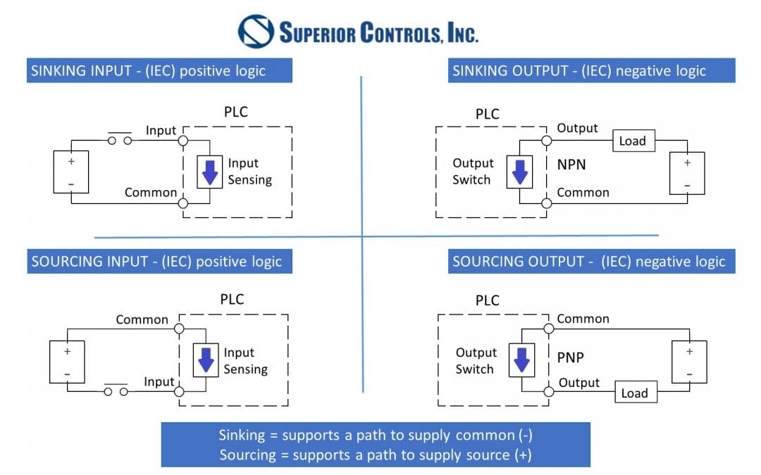
Sensor outputs come in two general configurations, sourcing and sinking. While there is no most common type—sourcing and sinking outputs are both frequently used across industrial control systems—it’s important to understand which type of sensor output is being connected to any given PLC input, because the PLC is also designed to either sink or source current.
A sourcing sensor output is able to source current to the PLC because the sensor’s internal switching device connects the signal wire directly to the DC power supply. This allows conventional current to flow out of the sensor terminal and into the PLC input. The sinking output uses an internal switching device that connects the signal wire to ground, allowing it to sink current from an active PLC input and return it to the common power supply ground.
While sourcing inputs and outputs usually make use of PNP transistors and sinking inputs/outputs make use of NPN transistors, there are inputs and outputs with the exact opposite configuration. The type of transistor is less important than the functional nature of the input or output, that is, whether it acts as a source or sink.
Complementary Configurations: Source vs Sink
Inputs and outputs should always be matched with their opposites; for example, a sourcing sensor output should be connected to a sinking PLC input to complete a closed-loop circuit.
The distinction on the PLC input between sourcing and sinking depends on how the common terminal is tied:
Sinking PLC Input: If the common terminal is tied to ground, the inputs will be sinking. Current flows from the sourcing sensors, through the PLC input point, and out the PLC common terminal to ground.
Sourcing PLC Input: If the common terminal is tied to +24VDC, the PLC will provide current to the sensor. Current flows out of the PLC input point, into the sinking sensor, and down to the ground reference.
Neither configuration is better than the other; it’s primarily a standard preference based on regional practices. For instance, PLC inputs are dominant in ICS architectures in Europe whereas sinking sensors with sourcing inputs are more dominant in North American automation systems as well as in parts of Asia. It’s a matter of ensuring all the devices are configured correctly to prevent damage.
Connecting Same-Sided PLC Inputs & Sensor Outputs
Connecting the sensor to the PLC becomes a challenge when both the sensor output and PLC input are either source-source or sink-sink. In these setups, both devices are either trying to push voltage or waiting for a ground connection, resulting in zero current flow.
It’s definitely possible to connect them, and there are three common strategies available:
1. Interposing Modules or Signal Converters
A module with selectable inputs and outputs can be used to isolate the PLC inputs from the sensor outputs. By placing an interposing relay between the devices, a sourcing sensor can energize the relay coil while the relay’s dry contact switches a sourcing PLC input to ground. This effectively matches signal types without direct coupling.
2. External Pull-Up or Pull-Down Resistors
Another, less elegant approach is to use a resistor to source or sink current. For sink-sink, a pull-up resistor can be added between the signal wire and +24VDC, and for source-source, a pull-down resistor can be added between the signal wire and ground.
While this solution can work, be aware that it alters signal logic. Because the resistor pulls the input line to the active state when the sensor is idle, the controller logic is inverted.
3. Open-Collector Sensor Configurations
An open-collector sensor output involves a circuit containing an NPN transistor oriented with the collector at the output pin and the emitter tied internally to ground. No internal voltage references to the supply exist within the sensor housing, so the output can only indicate a low state by pulling the collector pin down to ground when on.
To allow indication of a high state when interfacing with devices that don’t supply their own wetting voltage, an external pull-up resistor connected to the supply voltage will be required. This signal conversion can also be accomplished using an LED indicator or relay coil as the load.
Special Considerations for Mismatched Controls: AC Inputs & Safety
For alternating current (AC) PLC input cards, there is no sourcing or sinking distinction because the direction of electron flow alternates every half-cycle. Instead of the common connection and input pin arrangement found on the direct current (DC) cards, AC frequently isolates channels or uses dual-line AC optical couplers that respond to the RMS voltage regardless of polarity.
Sinking input cards do have a slight fail-safe advantage over the sourcing type in terms of short-to-ground behavior:
- Sinking PLC Inputs: A low signal caused by a broken signal wire or bare conductor touching the grounded metal machine frame will simply result in an off-state reading, causing the system to fail safely in a de-energized condition.
- Sourcing PLC Inputs: If a wire break or short-to-ground occurs on a sourcing input loop, current flows directly from the PLC’s internal +24VDC supply through the fault to frame ground. Without proper protection for the circuit, this short can blow internal card fuses and damage the power supply.
For this reason, sourcing input cards need a fuse between the sensor (as a voltage source) and PLC input terminals to prevent PLC or power supply damage during ground faults.
Common Sourcing/Sinking Mistakes to Avoid
When connecting sensors to PLC inputs, mismatches are a frequent source of issues. Avoid these common pitfalls:
- Using incompatible logic types: Connecting a sinking input to a sourcing sensor (or vice versa) can prevent the signal from registering correctly.
- Ignoring voltage and current ratings: Each sensor and PLC input has specific electrical requirements. Exceeding them can damage the device.
- Overlooking cable run effects: Long cables can cause voltage drop or signal degradation, particularly in high-current loops.
- Skipping documentation checks: Always verify the PLC input type against the manufacturer’s datasheet before wiring.
Quick Troubleshooting Tips for Sourcing/Sinking Issues
Even with careful planning, issues may arise during setup. Use these troubleshooting tips to quickly isolate and resolve problems:
1. Test Sensor Output with a Multimeter:
- Disconnect the signal wire from the PLC.
- Power the sensor, then trigger the target.
- Measure the voltage between the signal wire and 0VDC. If you read +24VDC when triggered, it is a sourcing sensor. If you read 0, it’s a sinking sensor.
2. Verify PLC Input Channel Behavior:
- Measure voltage across the input point and COM terminal.
- If the COM terminal is wired to 0VDCm applying +24VDC directly to the input terminal should light up the input LED, confirming a sinking input channel.
3. Check Ground Loops & References:
- Ensure the DC power supply powering the PLCs shares a common ground reference with the supply powering the PLC I/O card. Isolated power supplies without a common DC ground will prevent current loops from completing.
4. Isolate and Bench-Test:
- Run each sensor independently on a bench supply to confirm the switching behavior before terminating wires into a live control system panel.
Creative Control & Integration Strategies for PLC Configurations
Mastering the difference between sourcing and sinking configurations ultimately comes down to understanding how current flows through your control loop. While matching a sourcing or sinking output to the opposite input type is ideal, trying to connect same-type inputs and outputs isn’t a reason for panic. These situations require a little bit of creative engineering to allow the signal to match the PLC input. The problem is nothing that hasn’t already been solved – experienced control system integrators can help evaluate the most practical solution for a control system hiccup like this.