Author: Kevin Tom, E Tech Group lead automation engineer
Pharmaceutical control system integration: Fixing a blind spot in the process design helped user requirements for a heat exchanger control system. A control system may not be able to fix a faulty process.
Learning Objectives
- A system integrator was tasked with fixing a control system flaw for a pilot plant at a large pharmaceutical company.
- The integrator had to make several changes to the temperature control unit (TCU) to compensate for different variables with the liquid nitrogen flow.
- Thorough initial design and investigation helps prevent a scramble at the end of a project end to patch design holes.
System Integration Insights
- System integrators are often the last people involved in an automation project, which gives them a unique perspective on operations. That perspective is a double-edged sword, though, and can be problematic if there are design flaws in the system.
- In this case study, the system integrator had to make several changes to the temperature control unit (TCU) to compensate for the liquid nitrogen flow, which resulted in a few challenges that had to be addressed.
- The adage of automation always coming last may well be true, but the system integrator can avoid some pitfalls if the initial design and investigation is thorough.
A workable process design is the foundation for successful control system design. That can conflict with the timing of the old system integrator adage about new plant construction: “Automation always comes last.” It’s only after everything else is put in place that the system integrator can step in to install and test the control system, so they’re often the last member of the construction team.
However, what happens when the system integrator encounters a conflict between the process design left to them and the practical operation of the control system? How can control system user requirements be met when there’s a blind spot in the process design?
Unfortunately, there’s no one-size-fits-all solution.
Sometimes, it means going back to the drawing board and redesigning the affected parts of the process. At other times, it’s up to the system integrator to bridge the gap and modify the control system in the field to work around a flaw in the original design.
Consider a situation where the system integrator was tasked with bridging this design gap for a pilot plant at a large pharmaceutical company and follow the challenges and iterative development process that led to the end result.
The original process design: Temperature control loops
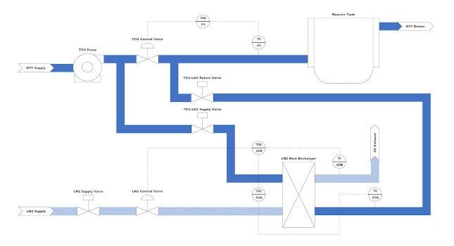
The centerpiece of the pilot plant was a suite of reactor tanks which each used a temperature control unit (TCU) to regulate reactor temperature. The TCUs use a heat transfer fluid that can be cooled to extremely low temperatures using liquid nitrogen. When the liquid nitrogen cooling control scheme is initiated, the heat transfer fluid is redirected to a liquid nitrogen heat exchanger to be cooled down to temperatures as low as -78 °C before returning to its reactor tank (Figure 1).
The initial control scheme provided by the design engineers on the project consisted of two temperature control loops: a feedback loop at the TCU (TIC-01) and a cascade loop at the liquid nitrogen heat exchanger (TIC-02A/B). The TCU control loop setpoint could be set to a wide range of temperatures, but if set below -40 °C, the liquid nitrogen cooling scheme would kick off. Block valves would open to divert heat transfer fluid to the liquid nitrogen heat exchanger while the TCU control loop (TIC-01) would modulate a control valve to divert heat transfer fluid away from the heat exchanger if the TCU temperature (TI-01) became too cold.
Once flow was established through the liquid nitrogen heat exchanger, the liquid nitrogen supply valve would open, and the liquid nitrogen heat exchanger loop (TIC-02A/B) would modulate a control valve to allow liquid nitrogen to enter the heat exchanger. The cascade loop (TIC-02A/B) used the heat exchanger nitrogen outlet temperature (TI-02B) as the process variable for the inner loop (TIC-02B) and the heat exchanger heat transfer fluid outlet temperature (TI-02A) as the process variable for the outer loop (TIC-02A). The design engineers originally specified a fixed setpoint of -78 °C for the heat transfer fluid exiting the exchanger.

Figure 1: Simplified process flow diagram of the liquid nitrogen cooling control scheme.
Fixing a flaw in the control design
Running this control scheme for the first time quickly revealed a key flaw in the original design. Operating the TCU with liquid nitrogen cooling at temperature setpoints warmer than -78 °C resulted in a low flow condition at the heat exchanger. Because the control valve manipulated by the TCU control loop acts as a bypass valve, heat transfer fluid flow to the exchanger decreases in response to low TCU temperatures (TI-01), resulting in increasingly less heat transfer fluid flowing through the exchanger. Eventually, the flow gets so low the liquid nitrogen freezes the little heat transfer fluid left in the exchanger. The design seemed only prepared to deal with TCU temperature setpoints at or near the -78 °C exchanger setpoint and did not account for large temperature differentials between the TCU and heat exchanger setpoints.
It became apparent the solution to this problem involved manipulating the fixed -78°C setpoint at the heat exchanger to allow for warmer setpoints at the TCU. Using trends to compare the heat transfer fluid temperature at the TCU (TI-01) versus that at the heat exchanger (TI-02A), a fixed setpoint offset was implemented for each TCU to avoid the low flow condition at the heat exchanger while still providing enough liquid nitrogen to lower the TCU temperature (TI-01) to its setpoint.
For example, for a fixed setpoint offset of 5 °C, setting the TCU setpoint to -50 °C would result in a heat exchanger setpoint of -55 °C. Each TCU seemed to settle on a different setpoint offset due to differences in tank size and pipe length to the heat exchanger, but after optimizing the offset, the TCUs could run with liquid nitrogen cooling at the warmer temperature setpoints.

Figure 2: Conceptual graph illustrating the different methods of setpoint offset tracking used to model the relationship between the TCU and heat exchanger temperatures. The highlighted region represents the “Goldilocks” zone in which temperature control is possible. In the area above the highlighted region, the heat exchanger setpoint is too cold, so the TCU bypass valve opens too widely in response, causing the heat transfer fluid to freeze. In the area below the highlighted region, the heat exchanger setpoint is too warm, so the TCU temperature setpoint is never reached. The fixed offset method, shown in blue, performed well in the warmer TCU temperature setpoint range, but at colder setpoints, there was insufficient cooling to reach setpoint. The linear offset method, shown in red, worked well at the warmest and coldest TCU temperature setpoints in the range, but at mid-range setpoints, the heat transfer fluid would eventually freeze. Ultimately, the quadratic offset method, shown in black, performed the best, successfully allowing the TCU control loop to control the temperature across all setpoints in the liquid nitrogen cooling range.
Another control system design hurdle
The liquid nitrogen freezing problem was fixed; however, a new issue arose. Previously, the TCUs could operate near the fixed -78 °C heat exchanger setpoint, but after adding the setpoint offset functionality, the TCU was unable to reach these colder setpoints. The problem was the differential between the heat transfer fluid temperature at the TCU (TI-01) and that at the heat exchanger (TI-02A) increased at colder temperatures.
While a fixed setpoint offset of 5 °C may have worked for TCU setpoints near -50 °C, but for TCU setpoints near -70 °C, the setpoint at the heat exchanger needed to be 8 or 9 °C colder. To address this, the setpoint offset was modified to be dynamically based on TCU temperature setpoint. At first, a linear function was employed, but after several weeks of testing, a quadratic function was determined to best model this relationship. After implementing this change, the TCUs could consistently run at any setpoint across the entire liquid nitrogen cooling range.
Control system integration: Examine the process design first
This is one example where the system integrator had to deviate from the original process design and overhaul the control system in the field to meet user requirements. Any situation where there’s an information gap between the preliminary process design and the practical operation of the control system may require the project’s system integrator to step in and build increased flexibility and functionality into the control system to compensate.
Thorough initial design and investigation is key to avoiding a frenzied scramble at project end to patch up holes in the process design.
This case study originally appeared on Control Engineering’s website. Click here to view the original article.