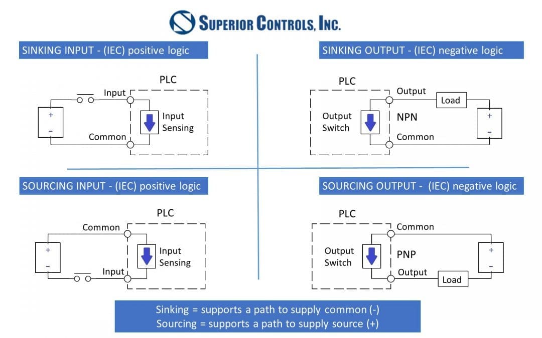
Sensor outputs come in two general configurations, sourcing and sinking. While there is no most common type—sourcing and sinking outputs are both frequently used—it’s important to understand which type of sensor output is being connected to any given PLC input, because the PLC is also designed to either sink or source current. A sourcing sensor output is able to source current to the PLC because it provides a voltage. The sinking output is pulled to ground, allowing it to sink current from an active PLC input.
While sourcing inputs and outputs usually make use of PNP transistors and sinking of NPN transistors, there are inputs and outputs with the exact opposite configuration. The type of transistor is less important than the functional nature of the input or output, that is, whether it is sources or sinks.
Complementary Configurations: Source vs Sink
Inputs and outputs should be matched with their opposite, for example, a sourcing sensor output should be connected to a sinking PLC input. The distinction on the PLC input between sourcing and sensing depends whether the inputs are tied to +24VDC or to ground. If tied to ground, the inputs will be sinking and will pull current from the sensor. If tied to +24VDC the PLC will provide current to the sensor.
Neither configuration is better than the other, it’s more a question of making sure all the devices are configured correctly to prevent damage. Connecting sensor to PLC becomes a challenge when both the sensor output and PLC input are either source-source or sink-sink. It is definitely possible to connect them, and there are a couple of options available:
Ways to Connect Same-Sided PLC Inputs & Sensor Outputs
- A module with selectable inputs and outputs can be used to isolate the PLC inputs from the sensor outputs is one possibility. Using the module, select the module input that matches the sensor output. Doing the same thing on the PLC input side will convert the incoming sensor signal into something the PLC can read.
- Another, less elegant approach is to use a resistor to source or sink current. While this solution can work, be aware there may be significant PLC programming accommodations because the resistor inverts the signal.
- An open-collector sensor output involves a circuit containing an NPN transistor oriented with the collector at the output pin. No internal voltage references to the supply exist, so the output can only indicate a low state. To allow indication of a high state, an external pull-up resistor connected to the supply voltage will be required. This can also be accomplished using an LED or relay.
- For alternating current PLC input cards, there is no sourcing or sinking type. Instead of the common connection and input found on the direct current cards, AC cards will have two connections for each input.
- Sinking input cards do have a slight advantage over the sourcing type because a low signal, like that received due to a wire break or ground fault, will not activate the input. Sourcing input cards need a fuse between the sensor (as voltage source) and PLC input terminals to prevent PLC or power supply damage if a short to ground develops from, for example, a wire break.
While matching a sourcing or sinking output to the opposite input type is ideal, trying to connect same-type inputs and outputs isn’t a reason for panic. These situations require a little bit of creative engineering to allow the signal to match the PLC input, but the problem is nothing that hasn’t already been solved.
