After reviewing part one of this three-part series, you now have a conceptual understanding of the S88 standard and its applications. If you haven’t yet read the first part of this series, check out S88 Specs, Part 1 of 3: An Introduction to the S88 Standard.
Illustrating the S88 Standard in Application
Understanding the S88 standard is only a piece of the puzzle. It can be difficult to fully grasp its implementation in process. Having a visual representation of a system utilizing Batch Control in manufacturing can add the next piece.
In this article, we discuss System Modeling under the S88 standard covering the Process, Physical and Procedural Control models, and how the combination of these models enables effective control, monitoring and automation of the process.
Control System Modeling Under the S88 Standard
Modelling is best illustrated using a simple example such as a manufacturing plant with three process trains. Each train is intended to support the same set of three units with each unit of the same type supporting the same set of actions. Variations in terms of size and output are permitted.
In this example, assume each train consist of a reactor, filter and recovery vessel.
Process Model
The process model in the S88 standard serves as a means of organization of the processing activities that are performed by the system i.e. process. The process is achieved using the physical equipment defined in the physical model and the recipes defined in the procedural control model.
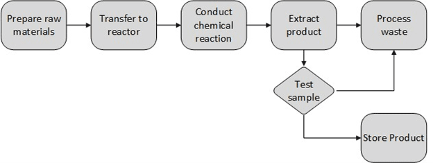
Fig. 1 Process Model
Here we could envision supplying ingredients, and reagents or solvents to the reactor, followed by chemical reaction and transfer of the product to the filter. The filter separates the product from the waste and transfers the waste for disposal recycling to the recovery vessel.
Physical Model
The physical model in the S88 standard represents the equipment and physical components involved in a process. In the case of a three-unit train, the physical model would consist of the following elements:
- Units: The three individual units of the train, each representing a specific function or process step: reactor, filter and recovery vessel.
- Connections: The physical connections between the units, including pipes, valves, and other relevant equipment.
- Sensors: Sensors placed at various points along the train to monitor parameters such as temperature, pressure, flow rate, and level.
- Output devices: Actuators responsible for controlling valves, pumps, motors, or any other components involved in the train’s operation.
The physical model is a representation of the train and its components, allowing for a better understanding of the system’s physical layout and interactions.
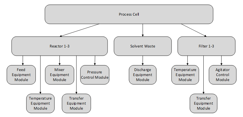
Fig. 2 Physical Model
Procedural Control Model
The procedural model in the S88 standard defines the sequential steps and actions required to execute a process. These steps form a recipe. In this simple example a recipe would contain the following unit procedures:
Step 1: Material Preparation Procedure
- Unit 1 Reactor: Start the pump and open the inlet valve to add materials into Unit 1. Maintain pressure and temperature.
Step 2: Product Separation
- Unit 2 Filter: Once Unit 1 has reached the desired operating conditions, start the transfer pump and open the inter-unit valve to initiate fluid transfer from Unit 1 to Unit 2. Once the material transfer is complete Unit 2 initiates the product separation sequence; send the solvents to the Solvent Waste vessel and retain the product the Filter vessel.
Step 3: Product Extraction
- Once Unit 2 product separation is complete transfer the final product out to temporary storage.
The procedural model outlines the sequence of steps and actions to be followed in the form of a recipe. Recipes rely on recipe Phases to interact with the control system Control Module and Equipment Module Phases which in turn interact with the physical devices through Control Modules and Equipment Modules.
The same recipe can be used on each of the trains. The trains do not have to be identical since the recipes are highly configurable. The units of the train must have the same capabilities, but they can vary in terms of size or output.
By combining the physical model and procedural model, the S88 standard enables effective control, monitoring and automation of the process. The interaction between Level 3 Batch Control and Level 2 Control System levels is strictly defined under S88 standard.
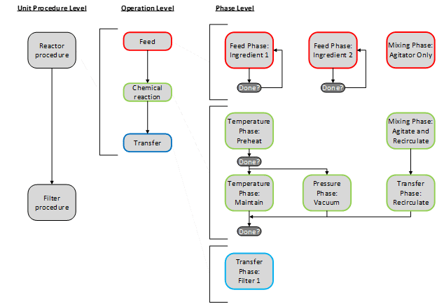
Fig. 3 Recipe Example
Note that one-to-one correspondence exists between the procedural model phases and equipment/ control module phases.
From Written Concept to Visual Application
We’ve almost come full circle, as we have now covered the S88 standard and how it can potentially be applied to a system model. But there’s one last piece that will really complete this picture in understanding how it functions within the framework for the control and automation of manufacturing processes.
In our final post of this series, we will address how the S88 standard defines various states that units or phases transition through during their operation and how they provide the standardized framework for interaction between recipe phases, control system equipment and control module phases.
For the final part in our S88 series, check out Part 3 of 3: Understanding S88 States. And for more on E Tech Group’s capabilities in the S88 standard, visit our S88 Batch Control Systems page.