After reviewing parts one and two of this three-part series, you now have a conceptual and visual understanding of the S88 standard and its applications. If you haven’t yet read the first two parts of this series, check out S88 Specs, Part 1 of 3: An Introduction to the S88 Standard and Part 2 of 3: System Modeling Under S88 Standard.
Transitioning S88 States Throughout Production
In this last entry, we’ll provide the final piece of the puzzle, bringing it all together. We’ll examine the progression through the numerous defined states associated with the manufacturing process as it aligns with S88 and the corresponding model.
Understanding S88 States in Control System Modeling
The S88 standard defines various states that units or phases can transition through during their operation. These states, categorized as an Initial State, and Quiescent, Final or Transient states, provide a standardized framework for interaction between recipe phases and control system equipment and control module phases.
Let’s explore some of the key states defined by the S88 standard:
Quiescent states
- Held
- Paused
Final States
- Aborted
- Stopped
- Complete
Initial State
- Idle
Transient states
- Starting
- Restarting
- Running
- Aborting
- Holding
- Pausing
The states listed here are the typical implementation. The procedural state model can be expanded or collapsed as permitted by the standard. The figure below shows the basic state diagram.
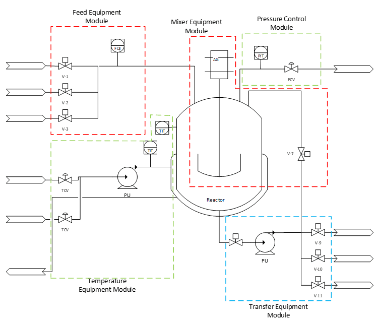
Fig.4 State Transition Diagram
SC Denotes State Change – state logic completes normally and the state advances as indicated by arrows. Text over the arrow Start, Resume etc. are external commands from batch application or internal to the control system or operator issued. The Hold, Stop, Abort are unique in that they act on multiple steps contained within the shaded rectangles.
Handshake signals are implemented between the control system and batch system through command and status bits. They are clearly defined for consistent behavior. Phase logic interface is implemented in equipment entities and batch applications pass the commands and state information back and forth.
For clarity one possible implementation is to match each acting state (name of state ending with ‘ing’) with a PLC subroutine.
For instance, one valid sequence of transitions is from Running to Holding to Held to Restarting and back to Running resulting in the sequence of events:
- Phase logic in the PLC receives a Hold command.
- Running subroutine is interrupted and Holding subroutine starts. Holding status is set to signal to batch application that the Hold request is being processed.
- Successful completion of Holding sequence results in a quiescent state of Held and status of Held transmitted to batch application.
- The Phase logic receives Restart command and transitions to Restarting by executing Restarting subroutine. Restarting sequence completes, which results in state change to Running and execution of Running subroutine.
Often application notes or code samples are available from S88 software vendors; see resources shared by Siemens, Rockwell Automation, ABB, Aveva, GE, DeltaV.
Implementing S88 Process Control for Batch Systems
In the example of a reactor, we identified five phases:
- Feed Phase
- Mixing Phase
- Temperature Phase
- Pressure Phase
- Transfer Phase
In the figure below, a representative P&ID diagram of a jacketed rector, we identified equipment and control modules. Each of the five phases controls modes of the corresponding module.

A correctly identified model should provide sufficient flexibility for the process designers to translate the process model into a control recipe in a familiar environment without a need to make any changes in the PLC code.
Bringing It Full Circle
Over this three-part series we have provided a beginner’s guide to the S88 standard, outlining the standard itself, what was responsible for its development, how it was visually implemented in a process model, and how production phases transition through varying states.
Follow the links at the top of the article for the other two parts in our S88 series, or Understanding the S88 Standard: A Comprehensive Guide for Beginners, for more, and visit S88 Batch Control Systems for more information on E Tech Group’s S88 capabilities.
References
- ANSI/ISA-88.00.01-2010 Batch Control Part 1: Models and Terminology
- NIST GCR 19-022 Formalizing ISA-95 Level 3 Control with Smart Manufacturing System Models, Leon F. McGinnis